
I had the privelege of operating the 1998 ARRL June VHF QSO Party with the Grid Pirates, K8GP. The operation took place near the summit of Spruce Knob, WV, FM08fq. Spruce Knob is a National Recreation Area, and is the highest point in the state of West Virginia.
I arrived an hour or two before the contest in driving rain, which really made driving the last nine miles of dirt road to the summit quite exciting. It was pretty much rain, fog, mist, and cold damp for almost the entire weekend. There was a break in the clouds for about forty-five minutes or so, starting around 1845 UTC on Saturday. As all stations were manned and the contest had just gotten underway, I took advantage of the moment and went on walkabout around the summit area and took some photos. It was the last time we saw the sun that weekend.
This was my first-ever VHF mountain-top contest experience. For someone who operates extensively from a point of low elevation in South Texas, it still amazes me how easy it was to work 400+ mile paths of 2M troposcatter...
These photos are copyright © 1998-2003 Kenneth E. Harker. All rights reserved.
|
|
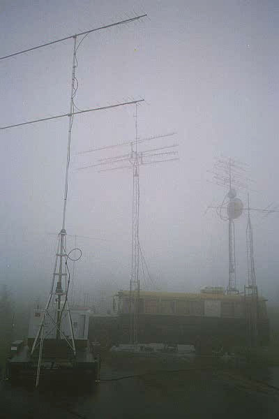
It was just starting to rain hard around 1730UTC. The trailer on the left holds a Create tower and a 15KW computer-controlled generator, owned by Owen K6LEW. The antennas are the 222MHz stack of C3I FO16-222 16-element yagis. The converted bus on the right was used for operations on the bands 222MHz and higher. The three towers on the bus held all the antennas for 70cm and up, as well as the mult station 6M beam. |
|
|
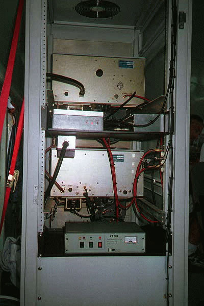
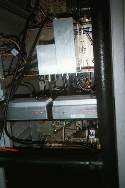
The back side of the rack in the low band bus. From top to bottom: Henry 144MHz amplifier, DEM 144MHz transverter, Henry 50MHz amplifier, SSB Electronics 50MHz transverter. Behind the panel at the bottom were a pair of Mirage brick amplifiers, each of which were used in line between a transverter and the high power amplifier. This equipment was for the two run stations, both of the mult stations had their transverters and high power amplifiers at the operating position. |
|
|
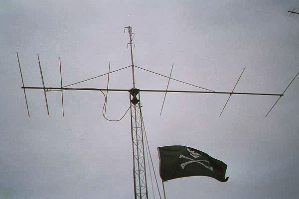
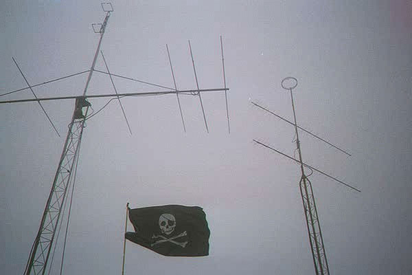
This is a 7-element C3I C7-50 6M beam on a 30 foot tower mounted on the rear of the low-band bus. The pirate flag, emblem of the Grid Pirates flies in the foreground, and was attached to its own flagpole. |
|
|
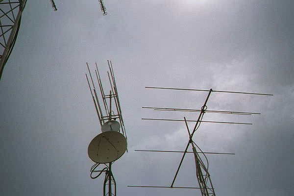
The microwave towers on the high-band bus. To the left from bottom up is a 4 foot dish for 5760 MHz, a 2 foot dish for 10 GHz, 4 72-element blowtorches for 2304 MHz, and 4 72-element blowtorches for 3456 MHz. To the right is the C3I C5-50 5-element beam used by the 50MHz mult station. Not shown is a pair of 45-element 903MHz loopers and a pair of 55-element 1296 MHz loopers, both on a third tower connected to the bus. |
|
|
You can see the secondary 222 MHz yagi and the top of Owen K6LEW's red truck, with a 6M Saturn 6 halo, 2M Sqloop, vertical antennas for 50 MHz through 1296 MHz and a large HF mobile antenna. |
|
|
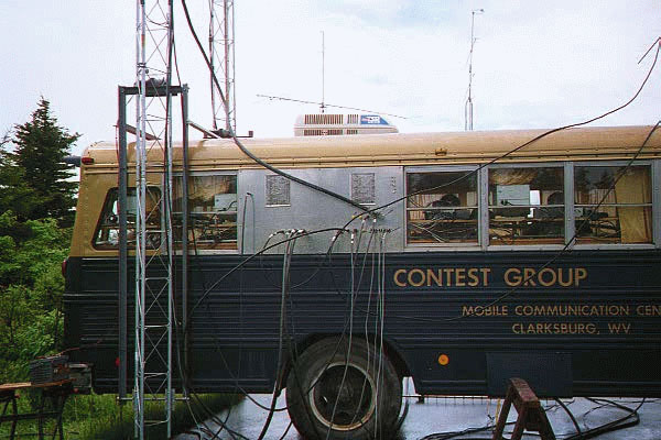
Here is a side view of the high band bus, with the coax entry panel and mounts for the towers connected to the bus. The shadowy figures to the right inside the bus are the microwave operators, K6LEW and K3LFO (left to right.) The antennas seen above the top of the bus are the C3I C7-50 on 50MHz to the left and a pair of C3I FO22-432's to the right on 432 MHz. |
|
|
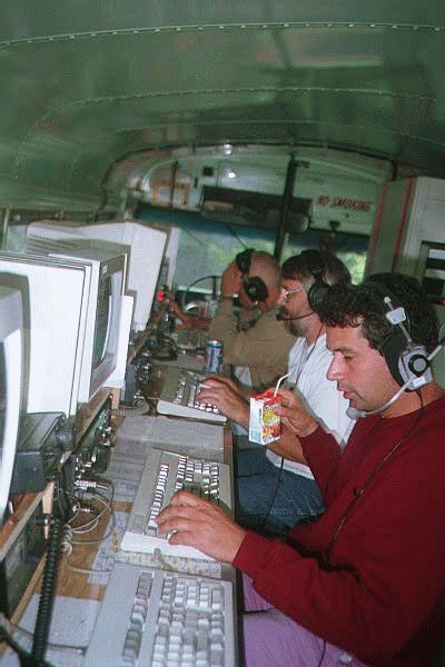
This was the scene inside the low band bus. Front to rear are Ken N4UK at the 2M run station, Terry WD8ISK at the 6M mult station, and Chris WA3HMK at the 6M run station. The keyboard in the foreground was the 2M mult station (unmanned at the time.) |
|
|
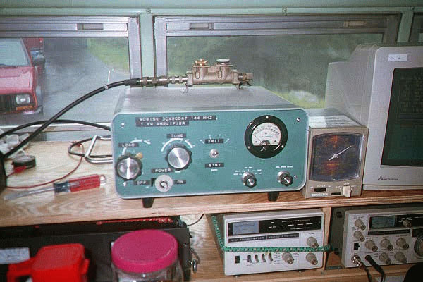
This is a shot of WD8ISK's travelling 2M amplifier, a homebrew 3CX800A built into a Heath SB200 case. This amp was used as the 2M mult station amplifier, but didn't see much use as it apparently had a relay problem. In the bottom right of the picture, you can see the Yaesu FT-107R and matching Yaesu FTV-107R transverter combination that served as the 2M mult station. In the bottom left is an Astron RS-50M power supply. |
|
|
Here is Chris WA3HMK operating at the 6M run station. The Yaesu FT-1000D was the IF rig, connected to a new-version SSB Electronics transverter and the Henry 8877 amplifier (both of which were rack mounted behind him.) The amplifier on his left was W4XP's 50MHz homebrew 8877 in a DTR2000 case, and was the amplifier for the 6M mult station. The Icom 706 to the left of the Yaesu FT-1000D was intended for 6M FM QSOs, but I'm not sure if any were actually made. Another Icom 706 was used to make at least a couple of dozen FM QSOs on 2M. |
|
|
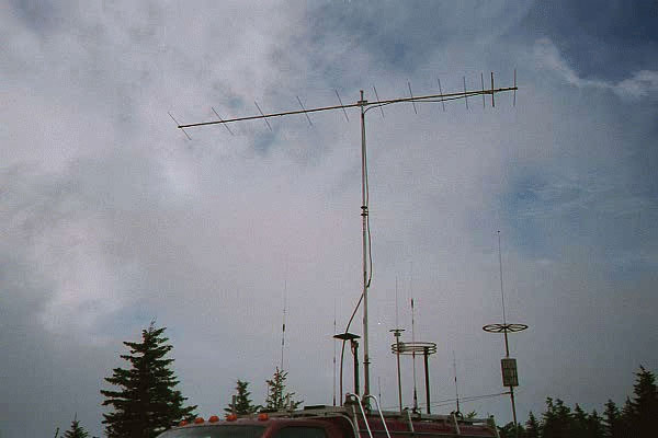
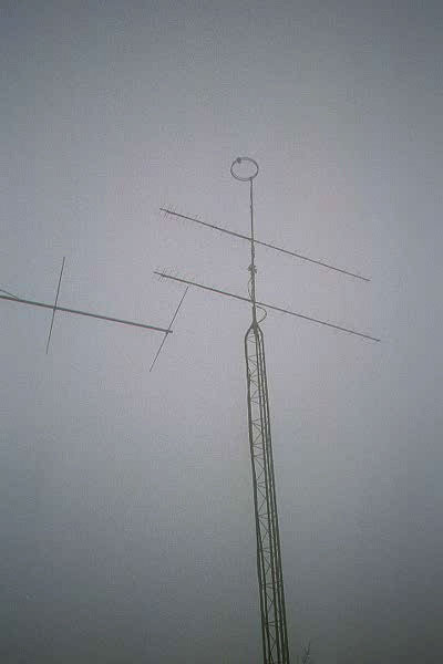
The tower in the middle holds a pair of C3I F022-432 70cm yagis with a 6M halo used used for omni receive mounted above them. The antenna parts in the left of the frame belong to the 6M run station's 7-element C3I C7-50 6M beam. |
|
|
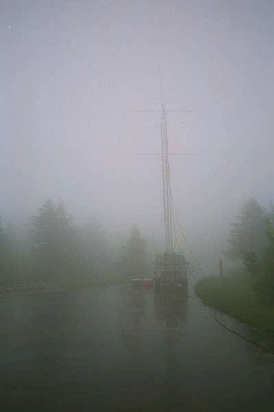
The brown van is holding a pair of C3I FO12-144 2M yagis barely visible through the fog and rain, mounted on a 30 foot tower. In the front of the van is a 20 foot tower with some vertical FM antennas for 6M and 70cm. |
|
|
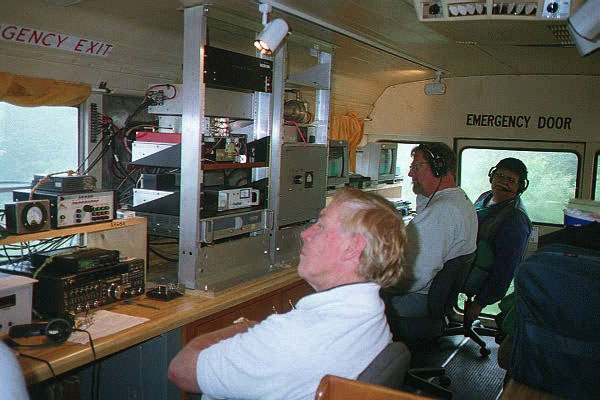
The scene inside the high bands bus. On the left, Owen K6LEW is sitting in front of the 2304MHz and up station. The IF radio was a Yaesu FT-736R, operating on 2M, being fed into the (very nicely crafted) homebrew switch box above it. The racks in the middle held all the microwave transverters and amplifiers, including the 500W 3CX600U7 amplifier for 903 Mhz and a KB2AH design, four-tube, water-cooled 7289 cavity amplifier for 1296MHz that put out 600 watts. Various TWTs and brick run 10-20 watts on 3456, 5760 and 10 GHz. On the right is Chuck W4XP at the 222MHz station, far right is Gene W3ZZ at the 432MHz station. Just out of frame to the left is James K3LFO at the 903/1296 MHz station. |
|
|
The back side of the rack in the high bands bus. In the middle of the frame are two Downeast Microwave transverters, one each for 222MHz (left) and 432Mhz (right.) Behind the two vertically-oriented boxes is the back side of the Lunar Link 432MHz amplifier. Below the transverters, you can see portions of the 222Mhz high-power amplifier. |
|
|
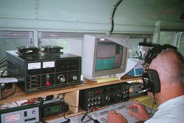
A picture of Ken KM5FA in front of the 2M run station Sunday afternoon. In the background, Chris WA3HMK is at the 6M run station. The four radios left to right were 2M mult station, 2M run station, 6M mult station, and 6M run station. You can also see the Icom IC-706 used for 2M FM QSOs on the shelf between the two 2M stations. In the rack on the right, one of the rack plates is removed, allowing access to the 144MHz run station amplifier. The large plate below it hides the 50MHz run station amplifier. At the bottom of the rack are two Mirage brick amplifiers, one each for 50MHz and 144MHz, placed in line between the transverters and the high-power amplifiers. |
|
|
Another shot of the 6M run station 7-element C3I C7-50 50MHz beam, and the pair of FO22-432 70cm antennas. The Jolly Roger flies in the foreground. |
|
Last Updated 26 June 2020 wm5r@wm5r.org |